|
AVO Valve Characteristics Meter
Mk1 Mk2 Mk3 Mk 1 Mk 2 Mk 3
Mark 1 Mark 11 Mark 111
|
|
Circuit Diagram, Service
Manual, Service
Information, Schematic Diagrams and Manuals |
|
For Repairing, Restoration and
Servicing of Vintage and Modern Electronic Equipment |
|
Manual
and Circuit
available
Details Below
As a Download
Click Here
|
|
Circuits
& Manuals
Military,
Radio, TV,
Amateur & Marine
World Wide Service
For
Lists Click Here
|
|
Use R/H scroll Bar
More information
below
Radio's For Sale
Click Here
Military and
Broadcast
Radio Ads Click
Here |
|
Military Radio Home
Click
Here If no Index to the left
|
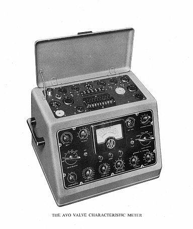
The AVO Valve Characteristic
Meter
The Manual Contains the
Following :-
The Basic Method of characteristic checking
The Basic Method of checking diodes and rectifiers
Insulation Testing
The Safety Cut-out
The Valve Panel and Selector Switch
Procedure for setting up valve base connections
Provision for new valve bases
Method used for prevention of oscillation
Special procedure for valves having internally connected pins
Diagram of Standard base pin connections
|
|
The controls on the front panel, their functions and operations
The ‘~ Control
The Electrode Leakage Switch
The Circuit Selector Switch
The Anode and Screen Voltage Switches
The Heater Voltage Switches
The Negative Grid Voltage Control
The Press Buttons
The Set Zero Control
The Meter Selector Switch
The Set mA/V Control The Anode Selector Switch
|
|
The Special Adjustment Panel at the rear of the instrument
General Procedure for testing a valve
Mains voltage adjustment and panel set up—cold and hot leakage tests—mutual
characteristic checks and gas tests—diode and rectifier tests made under load.
Instructions for testing specific valve types
Multiple diodes and rectifiers—double triodes and double pentodes—combined diode
and amplifying valves—frequency changers of heptode and hexode types—frequency
changers employing separate electrode assemblies.
|
|
The Use of the Link on the Back Panel of the Instrument
Tuning Indicators
Gaseous Rectifiers
Cold Cathode Rectifiers
Thyratons
Neon Indicators
General Precautions to be observed when using the Valve Characteristic Meter
Arrangements for the supply of additional valve data
Notes upon simple maintenance of instrument
Circuit diagram of Valve Characteristic Meter
List of Civilian Equivalents of Service Valves
Tabulated data for Valve Characteristic Meter and “AVO” Valve Tester
Tabulated data for testing Tuning Indicators on the Valve Characteristic Meter
Notes upon using the “AVO” Valve Tester with the tabulated data
Rectifiers Diodes
Multiple Electrode Assemblies
Frequency Changers
Testing l.4V Battery Valves
Accessories for use with the “AVO” Valve Tester
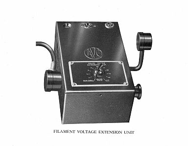
The Valve Tester Voltage Extension Unit
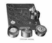
Valve Base Adaptors.
Plus AVO Valve Data Manual 1968 230 Pages |
Manual
and Circuit
available
Details Below
As a Download
Click Here |
AVO Valve
Characteristic Meter
Mk1 Mk2 Mk3 Mk 1 Mk 2 Mk 3
Mark 1 Mark 11 Mark 111
Manuals are Available
Worldwide as
a Download.
Please state which model when ordering
: -
"Mark One" "Mark Two" or "Mark Three" Thank
you.
Manual including circuits total of
between 105 & 108 pages
Plus the AVO Valve Data Manual 1968 230 Pages
Total between 335 & 338 Pages
Manual between 335 & 338 A4 pages worldwide
( For all Payment Options )
( Please Click the Payment Links Below )
|
|
We do all we can to provide
the very best that is available for you.
But in the unlikely event that any data should not be as you expected.
A refund is always available. Kind Regards Allen and Alanna. |
|