|
B40 B40A B40B B40C
B40D A B C D
AP57140/A/B/C/D AP57140 A B C D
Plus B41B B41 B Murphy Radio Receiver
|
|
Circuit Diagram, Service
Manual, Service
Information, Schematic Diagrams and Manuals |
|
For Repairing, Restoration and
Servicing of Vintage and Modern Electronic Equipment |
|
Manual and
Circuit
available
Details Below
As a Download
Click Here
|
|
Circuits
& Manuals
Military,
Radio, TV,
Amateur & Marine
World Wide Service
For
Lists Click Here
|
|
Use R/H scroll Bar
More information
below
Radio's For Sale
Click Here
Military and
Broadcast
Radio Ads Click
Here |
|
Military Radio Home
Click
Here If no Index to the left
|
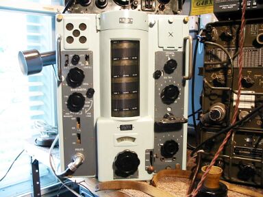
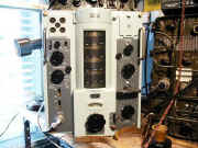
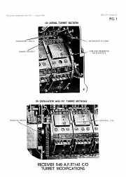
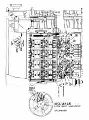
Murphy B40 Receiver
A.P.57140/A/B/C/D
Was the main unit in Receiver Outfits CDW and CAQ fitted in H.M. Ships and R.N. Shore Wireless
Stations.
Five versions of this unit were in service, B40/A/B/C and D.
The
B40/D was suitable for FSK.
They had five ranges, giving continuous
coverage from 650 kc/s to 30 mc/s. Intermediate frequency - 500 kc/s.
This
unit weighs 114 lbs-51.7kg.
The receiver is divided into three separate units as
follows :-
|
|
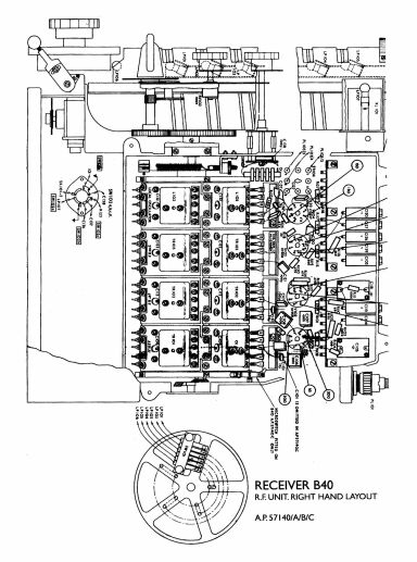
RF Unit Stage
1 RF Amplifier, incorporating
anti-cross- modulation control and harmonic frequency feed from the BFO
for calibration purposes. Stage 2 RF Amplifier, AGC
voltage applied.
Stage 3 Mixer
Employing a separate
oscillator which can be crystal controlled.
Fine adjustment of oscillator
is provided in the B40/D, the B40/D had the input circuit modified for
Common Aerial Working. |
Manual and
Circuit
available
Details Below
As a Download
Click Here |
IF Unit
A three position
band-width switch allows for IF pass bands of 8 kc/s (wide) and 3 kc/s
(narrow) in all units.
The third position of this switch incorporates an
audio note filter (band-pass 200 c/s, center frequency 1000c/s) in the
B40A; the 1 kc/s crystal band-pass filter is substituted in units B/C and
D.
Power Supply
115/230volts 40/60 c/s AC. Power consumption:- 80 watts
Loudspeaker :- 2.5 watts.
Ships control system
35milli watts.
Telephone
14 mW.
|
|
The B40 B40A B40B B40C B40D A B C D
A.P.57140/A/B/C/D Manual for A P. 57140 Series Receiver
Including all circuits layouts and alignment in 372 pages.
Contains the Following : -
Part I
Chapter 1 Operating Instructions
Chapter 2 Brief Technical Description
Chapter 3 Detailed Circuit Description
Chapter 4 Receiver Pattern Differences
Part 2
Chapter 5 Dismantling the Receiver
Chapter 6 Alignment
Chapter 7 Performance Tests
Chapter 8 Repair Data for Mark 4 Plugs and Sockets
Chapter 9 Repair Data Tuning Drive Mechanism
Part 3
Illustrations Components Lists and Coil Data
|
Manual and
Circuit
available
Details Below
As a Download
Click Here
|
|
|
B40 B40A B40B B40C B40D A B C D
AP57140 A.P.57140/A/B/C/D Manual
Manuals are Available
Worldwide as
a Download.
This condensed version includes circuits, component lists, layouts, alignment etc and differences for the above models
all the necessary data.
Plus
the B41B
B41 B A.P.57141B circuit.
Manual 372 A4 pages worldwide
( For all Payment Options )
( Please Click the Payment Links Below ) |
|
We do all we can to provide
the very best that is available for you.
But in the unlikely event that any data should not be as you expected.
A refund is always available. Kind Regards Allen and Alanna. |
|