|
BC-611 BC-611-A BC-611-B
BC-611-C
BC-611-D BC-611-E BC-611-F
Radio Set
SCR-536 SCR-536-A
SCR-536-B
SCR-536-C SCR-536-D SCR-536-E SCR-536-F
|
|
Circuit Diagram, Service
Manual, Service
Information, Schematic Diagrams and Manuals |
|
For Repairing, Restoration and
Servicing of Vintage and Modern Electronic Equipment |
|
Manual
Circuit and
Operation Instructions
available
Details Below
As a Download
Click Here
|
|
Circuits
& Manuals
Military,
Radio, TV,
Amateur & Marine
World Wide Service
For
Lists Click Here
|
|
Use R/H scroll Bar
More information
below
Radio's For Sale
Click Here
Military and
Broadcast
Radio Ads Click
Here |
|
Military Radio Home
Click
Here If no Index to the left
|
BC611 BC-611-A BC-611-B BC-611-C BC-611-D
BC-611-E BC-611-F
Radio Set
SCR536 SCR-536-A SCR-536-B SCR-536-C
SCR-536-D SCR-536-E SCR-536-F
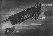
The Radio Set SCR-536 A B C D E or F consists of a five-tube, low-power, dry-batery-operated radio receiver and transmitter, and
accessories.
It is designed for amplitude-modulated. two-way communication over short distances. It is intended primarily as a handietalkie for foot combat troops.
The radio set is turned on by extending the antenna.
When thus connected to its internal dry-battery power supply, the radio set functions as a receiver. Pressing the press-to-talk switch converts the receiver circuit to a transmitter circuit.
The earphone provides sidetone so that the operator listens to his own voice when transmitting.
The set may be held in either hand when operating, although it is designed and balanced for
left hand operation.
The microphone and earphone are attached to the case in such a manner that the set resembles a telephone handset. In addition, later models of Radio Set SCR
536 F are equipped with jacks to permit coupling an external microphone and headset.
An adjustable carrying strap is attached to the case of Radio Set
SCR 536 for slinging and to provide additional support when used in the operating position.
The total weight of the set, including batteries as hand-carried for normal operation is 5.5 pounds.
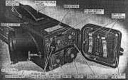
Technical Characteritics of Radio Set SCR 536
Radio Set SCR-536 is crystal-controlled on both reception and transmission, and will operate over the frequency range of 3.5 to 6.0 mc (megacycles).
However, each unit is adjusted to operate at only one frequency in this band by proper choice of plug-in crystals and coils
followed by pre-tuning adjustments.
The coil and crystal changes and the finer adjustments necessary to accurate pre-tuning
cannot he made by the operator, but are preset by authorized maintenance and repair personnel.
Frequency range
3.5 mc/s to 6.0 mc/s (any one of 50
channels)
Transmitter type crystal-oscillator power-amplifier
Receiver type crystal-controlled superheterodyne
Type of signal transmitted voice
Types of signals received voice and tone
Receiver intermediate frequency 455 kc
Distance range:
Over land 1 mile
Over salt water 3 miles
Type of modulation amplitude
Number of tubes 5 (only 4 used for transmitting )
Antenna 40-in, telescopic rod
Weight (with coils, crystals, and tubes, but without
batteries) 3.85 lb.
POWER SUPPLY.
Battery BA—37 (filament supply) 1.5 v
Drain while receiving 250 ma
Drain while transmitting 300 ma
Battery BA—38 (plate supply) 103.5 v
Drain while receiving 11 ma
Drain while transmitting 35 ma
Battery life 19 hr
single day
Weight:
Battery BA—37 0.5 lb
Battery BA—38 1.1 lb
|
|
|
Manual
Circuit and
Operation Instructions
available
Details Below
As a Download
Click Here |
| The Manual Contains the
Following :-
PART ONE. INTRODUCTION.
Description of Radio Sets SCR 536 A B C D E and F.
General
Technical characteristics of Radio Set SCR 536
Frequency Spectrum Chart
Table of components
Shipping weights and dimensions of packed sets
Housing
Power supply
Chassis
Controls
Moisture seals
Differences in models
Installation of Radio Set SCR 536
Unpacking and checking
Installation
Repacking
PART TWO. OPERATING INSTRUCTIONS.
Controls and their use
General
Turning set on and off
Receiving and transmitting
Controlling volume
Tuning
Operation.
Starting procedure
Sighting
Camouflaging
Receiving
Transmitting
Net operation
Stopping procedure
Equipment performance check list.
Purpose and use of check list
PART THREE. MAINTENANCE INSTRUCTIONS.
Preventive maintenance techniques. Meaning of preventive maintenance Description of preventive maintenance techniques
Itemized preventive maintenance.
Introduction
Preventive maintenance tools and materials
Exterior of Radio Set SCR 536
Item 2, antenna
Item 3, inside bottom cover
Item 4, chassis and interior of Radio Set SCR 536
Preventive maintenance check list
Factors determining preventive maintenance periods
Lubrication.
Lubrication instructions
Recommended lubricants for camouflaging and waterproofing
Moisture proofing and fungi proofing.
Problems encountered
Treatment
Step-by-step instructions
Moisture proofing and fungi proofing after repairs
Waterproofing.
General
Procedure
Materials required
PART FOUR. AUXILIARY EQUIPMENT.
Operating accessories
Battery BA—30 filament supply
Inclement weather protection
Expedient antenna
Equipment for use with external jacks
Maintenance Equipment ME—36
Homing Modification Kit MC-619.
General
Components
Installation
Operation
Theory of equipment
Mounting bottom plate
Pretuning
Moisture proofing and fungi proofing
Moisture proofing and fungi proofing after repairs
Frequency conversion kits.
Frequency Conversion Kit MC—534
Frequency Conversion Kit MC—518
PART FIVE. REPAIR INSTRUCTIONS.
Theory of equipment
Block diagram of Radio Set SCR 536
Circuit description
Receiver r-f amplifier
Converter
I-f amplifier
Detector, automatic volume control and first audio amplifier
Receiver power output amplifier
Transmitter oscillator
Transmitter r-f amplifier
Microphone amplifier
Modulator
Press-to-talk switch
Trouble shooting.
General trouble-shooting information
Test Equipment IE—15—A
Test Stand FT—252
Test Case CS—81
Test Set I—56
Test Equipment IE—17
Test Unit I—135
Trouble-shooting procedures
Sectionalizing trouble in Radio Set
SCR 536
Sectionalizing trouble in receiver circuit
Sectionalizing trouble in transmitter circuit
Localizing trouble in receiver and transmitter circuits
Repairs.
Replacement of press-to-talk switch
Chassis removal
Replacement of microphone
Replacement of earphone
Replacement of on-off switch
Replacement of antenna
Replacement of resistor-capacitor cups
Replacement of tubes
Changing coils and crystals
Removal of eyelets
Replacement of IF transformer
Unsatisfactory equipment report
Alignment and adjustment.
General
I-f alignment using signal generator
I-f alignment using Test Unit I—135
Minimum test requirements for Radio Receiver and Transmitter
BC 611
Presetting
General
Setting up Test Equipment IE—15—A
Presetting receiver with Test Equipment IE—15—A
Presetting transmitter with Test Equipment IE—15—A
Checking for image frequency
Using Radio Set SCR_536 as signal generator
Crystal activity test
Presetting receiver with Test Equipment IE—17
Presetting transmitter with Test Equipment IE—17
Testing Batteries BA—37 and BA—38 with Test Equipment IE—l7
Receiver sensitivity
Receiver performance characteristics
Transmitter performance characteristics
Emergency alignment and presetting procedure.
General
Major test equipment components
Housing modification
Feedback capacitor
Receiver alignment
Transmitter alignment
Battery checking
Alignment of set used as signal source
APPENDIX I. REFERENCES.
Army Regulations
Supply publications
Technical Manuals on auxiliary equipment and test equipment
Painting, preserving, and lubrication
Camouflage
Shipping instructions
Decontamination
Demolition
Other publications
Forms
Abbreviations
Glossary
MAINTENANCE PARTS.
Maintenance parts for Radio Set SCR 536
Maintenance parts for Homing Modification Kit MC-619 |
|
|
Manual
Circuit and
Operation Instructions
available
Details Below
As a Download
Click Here |
BC-611-A BC-611-B BC-611-C BC-611-D BC-611-E BC-611-F
Radio Set SCR-536-A SCR-536-B SCR-536-C SCR-536-D SCR-536-E SCR-536-F
Manuals are Available
Worldwide as
a Download.
Manual containing 113 pages including the Circuits with Component
lists and layouts.
Manual 113 A4 pages worldwide
( For all Payment Options )
( Please Click the Payment Links Below ) |
|
We do all we can to provide
the very best that is available for you.
But in the unlikely event that any data should not be as you expected.
A refund is always available. Kind Regards Allen and Alanna. |
|