|
Yaesu FT-707 FT707 Transceiver
FP-707
FP707 Power Supply
FC-707 FC707 Aerial Antenna Tuner |
|
Circuit Diagram, Service
Manual, Service
Information, Schematic Diagrams and Manuals |
|
For Repairing, Restoration and
Servicing of Vintage and Modern Electronic Equipment |
|
FT707 Service Manual
including circuits for the
FP707 & FC707 Details Below
As a Download
Click Here
|
|
Circuits
& Manuals
Military,
Radio, TV,
Amateur & Marine
World Wide Service
For
Lists Click Here
|
|
Use R/H scroll Bar
More information
below
Radio's For Sale
Click Here
Military and
Broadcast
Radio Ads Click
Here |
|
Military Radio Home
Click
Here If no Index to the left
|
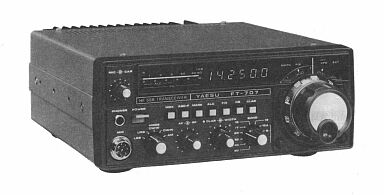
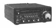
Yaesu FT-707
FT707
Transceiver
Transmitter and Receiver.
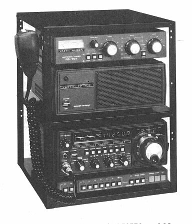
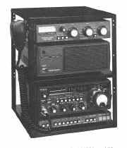
Yaesu
FP-707
FP707 Power Supply.
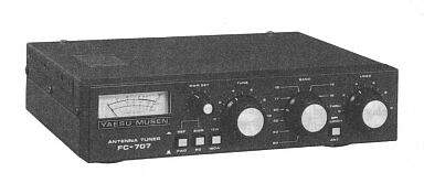
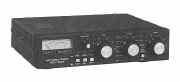
Yaesu FC-707 FC707 Aerial Antenna Tuner.
The Yaesu FT-707 is an all solid state transceiver for the HF amateur bands.
Featuring coverage of 80 through 10 meters, the FT-707 is designed for operation on SSB. CW and AM.
Nominal power output is 100 watts on SSB and CW. and 50 watts on AM.
The extremely compact size of the FT-707 makes this model particularly well suited for mobile or vacation use.
The receiver section includes a Schottky barrier diode ring module for excellent performance in the presence of strong signals.
A very-low-noise premix local oscillator circuit is used, which further contributes to optimum receiver performance.
Also included in the receiver is
variable IF bandwidth, using two 8 pole IF filters, allowing continuously variable adjustment of the
IF bandwidth, from 300 Hz to 2.4 kHz.
Six pole filters of 600 Hz and 350 Hz bandwidth (
- 6 dB) are available for contest and DX operators, with selection of the SSB filter or CW filter available on the CW mode.
The transmitter side features two rugged bipolar transistors with multiple protection in the final amplifier stage, with
band switched low pass filter networks.
Digital plus analog display of the operating frequency is provided.
The front panel meter consists of a string of bright discrete LEDs, for
monitoring of the received signal strength, relative power output. and the transmit ALC level.
Available options for the FT-707 include the FP-707 AC Power Supply, which provides the 13.3
volts DC required by the FT-707.
The FV-707DM external VFO, which provides twelve memory channels using a
synthesizer which allows scanning in 10 Hz steps.
The aerial tuner unit FC-707 Antenna Coupler.
Mounting bracket for mobile use.
|
|
|
|
| The Information Consists
of the
Following :-
The Maintenance Manual contains all circuits and printed board layouts for the FT-707
FT707 Transceiver.
Circuit
diagrams for the FP-707 FP707 Power Supply.
The FC-707 FC707 Aerial Tuner Unit
Instruction Manual with Circuit and Layout.
Yaesu FT-707 FT707 Transceiver
Yaesu FC-707 FC707 Aerial tuner unit
Yaesu FP-707 FP707 Power Supply
SECTION 1 — GENERAL
GENERAL DESCRIPTION
SPECIFICATIONS
SEMICONDUCTORS
FRONT PANEL CONTROLS AND SWITCHES
POWER SUPPLY FP-707
INTERCONNECTIONS
RELAY BOX FRB-707
ANTENNA TUNER FC-707
OPERATION
SECTION 2 — TECHNICAL NOTES
SIGNAL TRACING IN THE FT-707
RX FREQUENCY RELATIONSHIPS
CRYSTAL DATA
TX CONTROL LINE CIRCUIT
CIRCUIT DESCRIPTION
SECTION 3 — SERVICING
OUTER COVER REMOVAL
FRONT PANEL REMOVAL
REAR PANEL REMOVAL
100W PA UNIT REMOVAL
MAIN CHASSIS EXPLODED VIEW
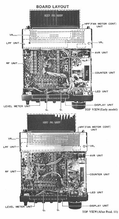
BOARD LAYOUT
SOLDERING AND DE-SOLDERING TECHNIQUE
CIRCUIT TRACING REPAIR
INSTALLATION: OPTIONS
CW FILTER INSTALLATION FIX (CRYSTAL CONTROLLED) OPERATION
MODIFICATIONS
S/N IMPROVEMENT ON 80M BAND
MODIFICATION TO ELIMINATE “CLICKING” NOISE ON CW
TX IMD DISTORTION IMPROVEMENT
MARKER MODIFICATION
PREMIX MODIFICATION
RECEIVER INPUT CIRCUIT MODIFICATION
WARC TX MODIFICATION
FREQUENCY COUNTER PRESET CHANGE
MAINTENANCE AND ALIGNMENT
FAULT IDENTIFICATION AND LOCALIZATION
TROUBLESHOOTING
RELAY CONNECTION INFORMATION
CIRCUIT BOARD LAYOUT AND TEST VOLTAGE
RF UNIT (PB-2093A/PB-2201)
IF UNIT (PB-2094A)
AF UNIT (PB-2095A)
AVR UNIT (PB-2099A)
COUNTER/DISPLAY UNIT (PB-2086A-3540/PB-2098-3540)
VFO ASSEMBLY (PB-2097A)
100W PA UNIT (PB-2013)
HPF/FAN MOTOR CONTROL UNIT (PB-2101)
LEVEL METER UNIT (PB-2100)
SW UNIT (PB-2102)
VR UNIT (PB-2103A)
SWITCH ASSEMBLIES
POTENTIOMETER ASSEMBLIES
SECTION 4 — REPAIR PARTS
PARTS LIST AND ORDERING FORMS
PARTS LIST
|
FT707 Service Manual
including circuits for the
FP707 & FC707 Details Below
As a Download
Click Here
|
|
|
|

|
This Service Manual Contains
154 pages covering the : -
FT-707 FT707 FP-707 FP707 & FC-707FC707
Manuals are Available
Worldwide as
a Download.
FT-707 FT707 Transceiver full Maintenance manual including all circuits and printed board
layouts.
FP-707 FP707 Power Supply circuit diagram only.
FC-707 FC707 Aerial Tuner Unit Instruction Manual with circuit diagram and layout.
All three included in one package, or to purchase the Aerial Tuner and Power Supply Information separately Click
Here
Manual 154 A4 pages worldwide
( For all Payment Options )
( Please Click the Payment Links Below ) |
|
We do all we can to provide
the very best that is available for you.
But in the unlikely event that any data should not be as you expected.
A refund is always available. Kind Regards Allen and Alanna. |
|