|
Marconi Universal
Bridge Type TF 868B TF868B |
|
Circuit Diagram, Service
Manual, Service
Information, Schematic Diagrams and Manuals |
|
For Repairing, Restoration and
Servicing of Vintage and Modern Electronic Equipment |
|
Manual with Circuits
available
Details Below
As a Download
Click Here
|
|
Circuits
& Manuals
Military,
Radio, TV,
Amateur & Marine
World Wide Service
For
Lists Click Here
|
|
Use R/H scroll Bar
More information
below
Radio's For Sale
Click Here
Military and
Broadcast
Radio Ads Click
Here |
|
Military Radio Home
Click
Here If no Index to the left
|
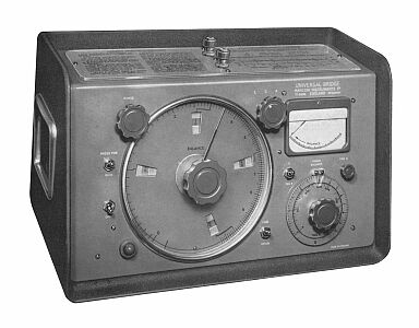
Marconi Universal
Bridge Type TF 868B TF868B
GENERAL
The Universal Bridge Type TF 868B is a direct reading instrument which measures values
of inductance from 1uH to 100 henrys, capacitance from 1 uuF to 100 uF, and resistance from
0.1 ohm to 100 M ohm.
The instrument employs a single dial for the measurement of inductance, capacitance, and resistance values.
Changing the setting of the LCR and RANGE selector switches automatically changes the dial calibration together with the bridge circuit conditions to suit the component under test.
|
|
For inductance and capacitance measurement the bridge is energized by an RC oscillator-amplifier that can be switched to 1 kc/s or 10 kc/s.
The
out of-balance bridge voltage, after amplification and detection, is displayed by a moving-coil meter on the front panel.
Measurement of inductance and capacitance is normally made at I kc/s; however, the use of 10 kc/s is an advantage, for example, when evaluating low-Q inductors.
When measuring resistance, a d.c. voltage is applied to the bridge.
The out-of-balance bridge voltage is interrupted at twice the supply frequency by means of a vibrator (or chopper) before being applied to the amplifier-detector circuits.
This system gives a high degree of sensitivity without the use of a high potential across the component.
A control, PHASE BALANCE, is provided for balancing out the resistive component when inductance and capacitance are being measured.
This control has two scales which are calibrated in Q and tan 8 respectively.
The scale in use is determined by the setting of the Q-TAN
switch.
The Q scale is calibrated from 0.1 to 10, and the tan scale from
0.001 to 0.1.
Q is normally used for inductors and tan for capacitors.
Q, also known as magnification factor or storage factor, is the ratio of reactance to resistance in a
series circuit, or susceptance to conductance in a parallel circuit.
Tan, also known as loss tangent, dissipation factor or D, is the reciprocal of Q.
Power factor, another term commonly used to express capacitor losses, is the ratio of resistance to impedance, or conductance to admittance, and differs from tan by less than I % when their values are less than 0.15.
For convenience, an instruction plate is fitted which interrelates values of Q and tan together with effective series and parallel values.
The plate also gives summarized instructions for operating the Bridge.
The test terminals are located on top of the instrument; the flat top provides a useful insulated platform for supporting the component to be tested.
When measuring inductive components, the usefulness of the instrument may be extended by the use of the D.C. Choke Adaptor, described below.
OPTIONAL ACCESSORY
D.C. Choke Adaptor Type TM 6113
With this Adaptor fitted to the Bridge terminals, an inductor in the range 100 mH to 100 henrys can be measured at 1 kc/s while a d.c. current up to 200 mA is passed through it from an external source.
The essential function of the Adaptor is to isolate the Bridge from the d.c. supply, while at the same time preventing the external circuit from appearing as an undesirable load across the test terminals.
When making a measurement, the introduced error is not likely to be greater than 3 % this can be ignored, or eliminated by a simple substitution method.
|
|
|
Manual with Circuits
available
Details Below
As a Download
Click Here
|
| The Information Consists
of the
Following :-
DESCRIPTION
GENERAL
OPTIONAL ACCESSORY
OPERATION
INSTALLATION
PRELIMINARIES
USING THE BRIDGE
Test Terminal Voltages
Connecting the Component
Resistance Measurement
Inductance Measurement
Using the D.C. Choke Adaptor (optional accessory)
Capacitance Measurement
NOTES ON INDUCTANCE MEASUREMENT
Use of 1 kc/s—l0 kc/s Switch
High Inductance Measurement
Low Inductance Measurement
Phase Balance
Q-tan and Series Parallel Conversion
NOTES ON CAPACITANCE MEASUREMENT
Residual Capacitance
Stray Capacitance
In Situ Measurements
Q-tan and Series Parallel Conversion
TECHNICAL DESCRIPTION
CIRCUIT SUMMARY
FUNCTION OF CONTROLS
Balance Control
Press for R x 10 Switch
Phase Balance Control
Fine-Q Control
Q-tan Switch
1 kcs—l0 kcs Switch
LCR Switch
Range Switch
CIRCUIT DESCRIPTION
Bridge A.C. Supply (Oscillator-Amplifier)
Bridge D.C. Supply
Measuring Bridge Circuits
Amplifier-Detector
Power Supplies
D.C. Choke Adaptor
MAINTENANCE
REMOVAL FROM CASE
MAINS INPUT ADJUSTMENTS
WORKING VOLTAGES .
REPLACEMENT OF VALVES
ADJUSTMENT AND LOCATION OF PRESET COMPONENTS
SCHEDULE OF TESTS
Apparatus Required
Insulation.
Oscillator-Amplifier
Measuring Bridge
Amplifier-Detector
Calibration of Main Balance Dial
Checking the Phase Balance Dial Calibration
Calibrating the Phase Balance Dial
COMPONENT LAYOUT ILLUSTRATIONS
GENERAL VIEW FROM REAR
UNDERSIDE OF CHASSIS—AMPLIFIER-DETECTOR
UNDERSIDE OF CHASSIS—OSCILLATOR-AMPLIFIER AND
POWER SUPPLY
RANGE SWITCH ASSEMBLY
BALANCE DIAL ASSEMBLY (EXPLODED VIEW)
DRAWINGS
COMPLETE CIRCUIT DIAGRAM
MEASURING BRIDGE CIRCUITS
D.C. CHOKE ADAPTOR
SPARES ORDERING SCHEDULE
ILLUSTRATIONS IN TEXT
UNIVERSAL BRIDGE CONTROLS
TEST TERMINAL VOLTAGE AT BALANCE FOR INDUCTORS
TEST TERMINAL VOLTAGE AT BALANCE FOR CAPACITORS
Q-TAN CONVERSION CHART
FUNCTIONAL DIAGRAM OF TF 868B
SIMPLIFIED RESISTANCE BRIDGE
SIMPLIFIED INDUCTANCE BRIDGE
SIMPLIFIED CAPACITANCE BRIDGE
SIMPLIFIED CIRCUIT OF D.C. CHOKE ADAPTOR
|
Manual with Circuits
available
Details Below
As a Download
Click Here
|
|
|
|
Manual with Circuits
available
Details Below
As a Download
Click Here
|
|
|
|
Manual with Circuits
available
Details Below
As a Download
Click Here
|
Marconi Universal
Bridge Type TF 868B TF868B
Manuals are Available Worldwide as a
Download.
Please note the TF868B advertised is very
different from the original model with out the B suffix.
Manual containing 47 pages including
all Circuits.
Manual 47 A4 pages worldwide
( For all Payment Options )
( Please Click the Payment Links Below )
|
|
We do all we can to provide
the very best that is available for you.
But in the unlikely event that any data should not be as you expected.
A refund is always available. Kind Regards Allen and Alanna. |
|