|
No 10 Crystal
Calibrator Frequency Meter
|
|
Circuit Diagram, Service
Manual, Service
Information, Schematic Diagrams and Manuals |
|
For Repairing, Restoration and
Servicing of Vintage and Modern Electronic Equipment |
|
Manual
Circuit and
Operation Instructions
available
Details Below
As a Download
Click Here
|
|
Circuits
& Manuals
Military,
Radio, TV,
Amateur & Marine
World Wide Service
For
Lists Click Here
|
|
Use R/H scroll Bar
More information
below
Radio's For Sale
Click Here
Military and
Broadcast
Radio Ads Click
Here |
|
Military Radio Home
Click
Here If no Index to the left
|
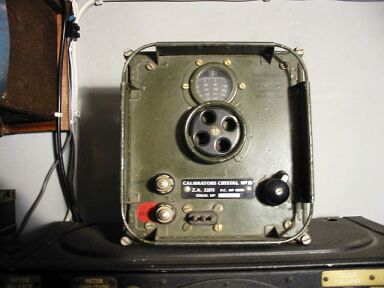
| No 10 Crystal
Calibrator Frequency Meter
The Calibrator, Crystal, No. 10, was designed primarily for the purpose of setting up a Wireless Set No. 62 accurately on a required spot frequency.
The calibrator functions as a C.W. wavemeter with continuous coverage over a nominal frequency band of
1.5 Mc/s to 10 Mc/s.
The calibrator power supplies are obtained from the socket engraved XTAL CAL on the Wireless Set No. 62.
The following facilities are available
(1) Selector switch in “ 500 Kc/s” position.
A crystal controlled oscillator which provides fixed frequency signals of 500 Kc/s and all harmonics of 500 Kc/s to beyond 10 Mc/s.
(2) Selector switch in DIAL “position.
In addition to the 500 Kc/s oscillator, a second and variable oscillator (250 Kc/s—600 Kc/s) is brought into circuit.
This enables all intermediate frequencies between 500 Kc /s and 10 Mc/s to be produced these frequencies are indicated on a calibrated dial on the front panel.
For identification purposes, the calibrator signal is modulated at about one cycle per second by means of a neon tube.
The output from the calibrator is taken from the terminal engraved AERIAL on the front panel.
2. Description
The calibrator is contained in a metal case (7 ins x 7 1/2 ins x 4 ins which has a protective rail around the front
panel.
The instrument, together with connecting leads, may be carried in a Satchels Signal No:
1T or No. 1.
When in use the calibrator may be placed in any convenient position, or may be rigidly attached to the Wireless Set No. 62 by means of a webbing strap.
Waterproof gaskets permit the equipment to be used under extreme
conditions of humidity and spray.
A desiccator may be fitted to ensure that the inside of the calibrator is maintained in a dry
condition.
The selector switch on the front panel has three positions : -
(1) OFF
(2) 500 Kc/s—to select the 500 Kc/s crystal controlled oscillator alone.
(3) DIAL— to select the 250 Kc/s to 500 Kc/s variable oscillator and the 500
Kc/s crystal controlled oscillator together.
When the selector switch is in the DIAL position, both oscilators are in circuit.
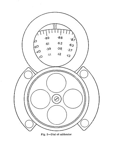
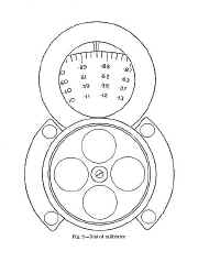
The frequency of the variable oscillator may be adjusted by a front panel control which also rotates a calibrated dial.
The engraved figures on this dial indicate the first and second decimal places of the frequency in
megacycles to which the calibrator has been set.
Four marks between adjacent figures on the dial enable the third decimal place of the frequency in
megacycles to be read, i.e. these latter marks are2Kc/s apart.
3. Frequency range
(1) 500 Kc/s to 10 Mc /s—by 500 Kc/s increments.
(2) Continuous 1.5 Mc/s to 10Mc/s (nominal).
The calibrator may actually be used up to 30 Mc/s.
4. Power supply and consumption
The calibrator is connected by Connectors 3 point No. 67 to the 3 point socket marked XTAL CAL at the bottom right-band corner of
the Wireless Set No. 62.
This supplies the calibrator with 12 volts D.C. and 300 volts D.C.
Consumption
Calibrator switched to 500 Kc/s - 10 mA H.T.
Calibrator switched to DIAL - 15 mA H.T.
L.T. - 0.3 A.
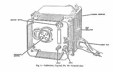
5. Controls
(1) Selector switch: 3 way; OFF—500 Kc/s—DIAL.
(2) Frequency control: frequency indicated on rotating dial.
(3) Power plug: 3-point.
(4) AERIAL: Output terminal.
(5) EARTH: Terminal.
There is also a 3 wire power connector (Connector 3 point No. 67) and a screened lead (Connector Twin No. 321) to
take the calibrator output to the aerial terminal of the Wireless Set No. 62.
These are stowed in a Satchel Signals No.
1T or No. 1.
6. Weights and dimensions
Weight: 5 lbs.
Dimensions (overall) : 7 ins. x 7 1/2 ins. x 4 ins.
|
|
|

|
|
|
|
The Manual Contains the
Following
CHAPTER I
GENERAL DESCRIPTION
1. Purpose and facilities.
2. Description
3. Frequency range
4. Power Supply and Consumption
5. Controls
6. Weights and dimensions
CHAPTER 11
OPERATOR’S INSTRUCTIONS
7. Connecting up
8. Setting up the Wireless Set No. 62
9. Using the Calibrator
CHAPTER 111
MAINTENANCE
10. General
11. Suggested daily tasks
12. The Desiccator
13. Removal of chassis
14. Valves
15. Fault location
Fault Finding Table
APPENDIX I
ILLUSTRATIONS
Fig. I. Calibrator, Crystal, No. 10—General View
Fig. 2. Dial of calibrator
Fig. 3. Internal view of calibrator
Fig. 4. Circuit diagram of calibrator
|
Manual
Circuit and
Operation Instructions
available
Details Below
As a Download
Click Here
|
No 10 Crystal
Calibrator Frequency Meter
Manuals are Available Worldwide as a
Download.
Working
Instructions contain 21 pages including Circuits
Component lists and Layouts.
Manual
21 A4 pages worldwide
( For all Payment Options )
( Please Click the Payment Links Below )
|
|
We do all we can to provide
the very best that is available for you.
But in the unlikely event that any data should not be as you expected.
A refund is always available. Kind Regards Allen and Alanna. |
|