|
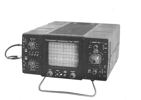
Telequipment Oscilloscope
D1010 & D1011
|
|
Circuit Diagram, Service
Manual, Service
Information, Schematic Diagrams and Manuals |
|
For Repairing, Restoration and
Servicing of Vintage and Modern Electronic Equipment |
|
Maintenance
Manual
with Circuits and
Operation Instructions
Details Below
As a Download
Click Here
|
|
Circuits
& Manuals
Military,
Radio, TV,
Amateur & Marine
World Wide Service
For
Lists Click Here
|
|
Use R/H scroll Bar
More information
below
Radio's For Sale
Click Here
Military and
Broadcast
Radio Ads Click
Here |
|
Military Radio Home
Click
Here If no Index to the left
|
Telequipment D1010 &
D1011 Oscilloscope
Manuals
also available for the following models :-
S22, D31, D31R, S31, S31R, D32,
S32A, S32AR, D43,
D43R, S43, D51, S51,
D52, S52, D54, D54R,
D56, D61,
D61A, DM63, DM64, D65, D66,
D67, D67A, D80, D83,
D1010, D1011, D1015, D1016 & Serviscope Minor.
Click
Here
GENERAL
DESCRIPTION
CATHODE RAY TUBE (CRT)
Rectangular flat faced CRT.
Display area 10 x 8 divisions (each division = 1.0cm)
Phosphor P31
Overall accelerating potential 1.8kV
Z Blanking 15V amplitude, d.c. coupled.
VERTICAL AMPLIFIERS
OPERATING MODES CH2
CH1 and CH2 alternate from lms/div to 0.2us/div.
CH1 and CH2 chopped from 0.2s/div to 2ms/div.
Chop or alternate selected automatically on SECS/DIV switch.
Add and subtract CH1 and CH2 algebraically. (D1011 only).
X-Y (D1011 only) Bandwidth is DC to 1.5MHz (-3db).
Phase error is <3° at 100kHz.
BANDWIDTH (-3db)
DC coupled DC - 10MHz
AC coupled 8Hz - 10MHz
Risetime 35ns (approx)
VERTICAL DEFLECTION
Calibrated (12 steps 1.2.5 sequence) 5mV/div to 20V/div ±5%
Input impedance 1Mohms in parallel with 45pF approx.
Maximum Input Voltage 500V peak a.c. or d.c.
Maximum Scan Amplitude 8 divs (6 divs at 10MHz)
x5 Gain Sensitivity (D1011 only) lmV/div [bandwidth DC to 4MHz (-3db)]
HORIZONTAL DEFLECTION
SWEEP SPEEDS
(19 steps in 1,2,5 sequence)
Normal 0.2s/div to 0.2us/div+5%
x5 Gain Maximum speeds of 40ns/div ±7%
On D1011 only a variable uncalibrated control provides continuous coverage between steps extending the slowest speed to 0.5s/div.
TRIGGER
Fully operational from 10Hz to 15MHz
Normal Level control will select any point on the waveform ± 4 divs about the mean d.c. level of the signal.
Automatic trigger on all repetitive waveforms >0.5 div and with mark space ratio <500: 1. The level control will select any point on the waveform between 10% and 90% (approx) of the peak to peak value.
TV TV field for sweep ranges 0.2s/div to 10us/div and TV line from
5us/div. to 0.2us/div. (Level control inoperative).
Source Internal. CH1 CH2 External
All positive or negative.
Internal Sensitivity 0.5 div
External Sensitivity 0.5V
EXTERNAL X
Bandwidth
DC coupled DC to 1.5MHz (-3db)
AC coupled 10Hz to 1.5MHz (-3db)
Sensitivity 1V/div approx.
Input Impedance 280k ohms in parallel with 30pF approx.
CAL OUTPUT SOCKET
Output Voltage 250mV ±2% peak to peak
Frequency At sweep repetition rate
Wave Shape Vertical step at screen centre
GENERAL
POWER REQUIREMENTS
Mains
Voltage 100V to 125V or 200V to 250V
Frequency 48Hz to 440Hz
Consumption 50VA approx.
SIZE
Height (stand retracted) 160mm
Width 300mm
Depth 420mm
WEIGHT 8kg
COOLING Convection combined with Heatsink mounting.
TEMPERATURE RANGE (AMBIENT)
Operational 0C to 40°C
|
|
|
|
|
The Manual Contains the
Following :-
SPECIFICATION
Cathode Ray Tube
Vertical Amplifiers
Horizontal Deflection
Cal Output Socket
General
OPERATION
General
Mechanical Features
Controls and Connection Sockets
CRT Graticule
Operating Voltage
Power Cord
First Time Operation
Setting the Controls
Switch On
Input Signal Coupling DC-GND-AC
Triggering
Trigger Level
Trigger Source
X-Y Display (D1011 Only)
Chop and Alternate Modes
EXT X
APPLICATIONS
General
Probe Adjustment
Peak to Peak Voltage Measurement
Voltage Measurement between Two Points
Instantaneous Voltage Measurement with Reference to Ground
Instantaneous Voltage Measurement with Reference to a DC Voltage
Time Duration Measurement
Frequency Measurement
Rise Time
Correction Formula for Fast Rise Time Waveforms
Phase Difference Measurement
CIRCUIT DATA
Introduction
Block Diagram-Circuit 1
CH1 and CH2 Vertical
Attenuators - Circuits 2-1, 2-2
Vertical Pre-Amplifier and
Channel Switching - Circuit 3
Vertical Output Amplifier - Circuit 4
Trigger Amplifier - Circuit 5
Sweep Generator - Horizontal Amplifier - Calibrator - Circuit 6
Power Supply - CRT - Blanking - Circuit 7
Interconnection Diagram - Circuit 10
WIRED ASSEMBLIES
Introduction
Circuit Boards
Part Numbers
PC242 - PC247 - PC253
PC244
PC245
PC246
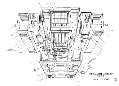
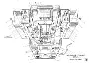
MECHANICAL PARTS
Parts List
Mechanical Assembly View 1
Mechanical Assembly View 2
MAINTENANCE AND FAULT FINDING
Introduction
Preventive Maintenance
General
Corrective Maintenance
General
Component Replacement
Dismantling Procedures
Top Cover Removal
Bottom Cover Removal
Vertical Amplifier Unit Removal
Electrical Shield (Vertical Unit) Removal
Horizontal Amplifier Unit Removal
Electrical Shield (Horizontal Unit) Removal
Heatsink Rear Panel Removal
Power Supply Board PC246 Removal
CRT Removal
Mains Board PC247 Removal
Front Bezel Removal
Handle Removal
Power Supply Fault-Finding and Repair
Equipment
Supply Malfunctioning
Fault-Finding Procedure
CRT Blanking Procedure
RE-CALIBRATION
Introduction
General
Calibrator
Tools and Equipment
RE-CALIBRATION PROCEDURE
Initial settings
DC Supply Line Voltages
CRT Controls
Vertical Amplifier
CH1 and CH2 Gain and Volts /Div Balance
x5Gain Balance (D1011 only)
Vertical Amplifier Input Compensation
X-Y Gain and Balance (D1011) only
Vertical Amplifier High Frequency Compensation
Internal Calibrator
Sweep Accuracy
Trigger Sensitivity
STANDARD OPTIONS AND ACCESSORIES
Introduction
Standard Options
Accessories
Rack Mounting D1010R / D1011R
|
|
|
Maintenance
Manual
with Circuits and
Operation Instructions
Details Below
As a Download
Click Here
|
Telequipment
D1010 & D1011 Oscilloscope
Manuals are Available Worldwide as a
Download.
The
Manual contain 73 pages including Circuits
Component lists and Layouts
Manual
73 A4 pages worldwide
( For all Payment Options )
( Please Click the Payment Links Below )
|
|
We do all we can to provide
the very best that is available for you.
But in the unlikely event that any data should not be as you expected.
A refund is always available. Kind Regards Allen and Alanna. |
|